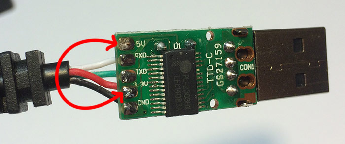
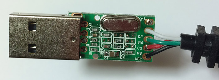
Use a modified USB to TTL cable based on the PL-2302 and modify it to support 3v!
This Prolific PL-2303 based USB to TTL adapter cable can be purchased from amazon for about $6
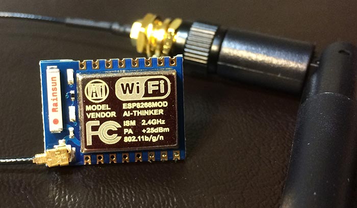
Seemingly, this is the cheapest ESP8266 "development kit" you can quickly get your hands on.
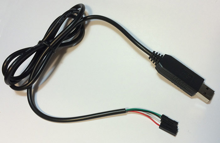
This cable comes wired by default for 5v and will DESTROY your ESP8266 device! You must unsolder the red wire from the 5v pad and move it to the 3v pad.
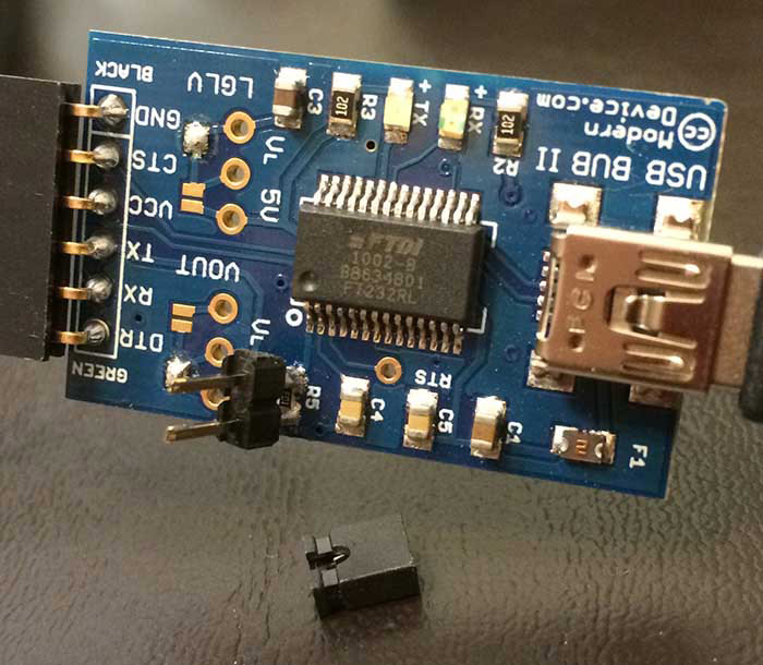
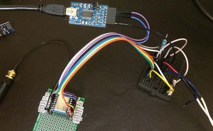
Modern Devices makes the USB BUB II device pictured below. Facilitating the TTL conversion is a FTDI chip. Bub is designed for arduino and jeelabs jeenode type communication, but can also be used with the ESP8266, but does require one modification as well.
Keep in mind our friend the 'Bub is also a 5v device by default and you must solder some resistors or something to convert VCC to 3v. I couldn't find any instructions so I used an external 3v power source instead.

Notice the jumper. I added that jumper to my USB BUB. There is a resistor on the tx line which is OK for arduino, but was causing communication to fail with the ESP8266.
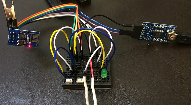
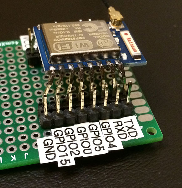
One issue is that the pin spacing on the ESP does not lend itself well to breadboards. I used a perf board to hold my ESP unit, but you can also use this technique to just add the pins and make the ESP unit breadboard friendly. First I pre-bent the pins, soldered the middle pin on each side, and worked my way out.

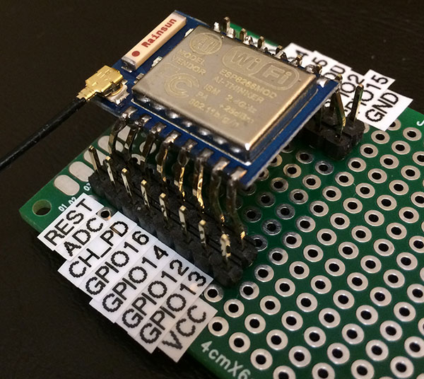
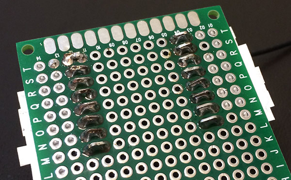
Using the pins poking through, I bent them to jump the solder pads
Once your cables/devices are properly modified it's off to the races! You can use this as a serial/uart wifi device with an arduino, but really - what's the point? Who wants to pass butter when you can upload your own firmware right into this sucker?!?
Download The Windows Dev Kit from here. There is a ESP8266.com forum post with detailed release info.
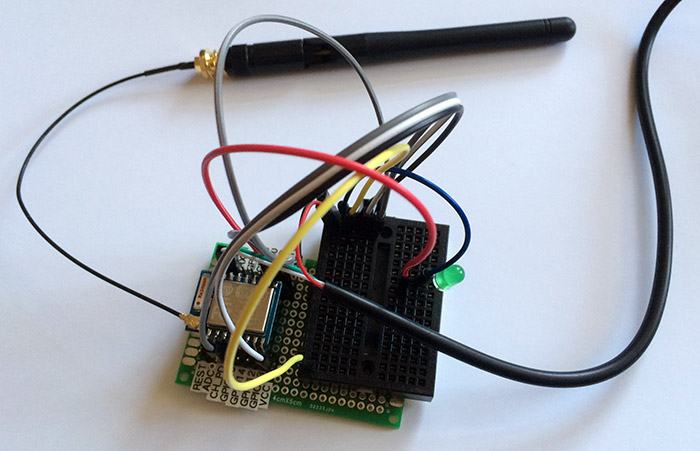
Here I added two switches, one for reset, and the other for firmware flashing. I hold the firmware flash button, then hit reset and after a second you can release the firmware flash button.