First I manually controlled the stepper motor via a rotary encoder.
Web UI
The device is controlled via webui which uses websockets to send messages to the esp32
One Set Printed
Here's the base design with 40 flaps printed on silk multicolor pla.
Motor Mounting
The blue cap on the motor is removed to allow more clearance inside the drum.
Here is a view inside the drum:
Magnet for Hall Sensor
A small magnet (1x3mm) is glued to the inside of the barrel to trigger the hall sensor. Note the correct pole must be facing the hall sensor- use a sharpie to mark the correct side!
Pro Tip! Use non-magnetic tweezers to set the magnet. The finer the better
Hall Sensor
The hall sensor is the cheapo module from amazon with the A3144E digital hall sensor.
Remove the pins from the board and solder wires directly to the board. For prototyping I soldered some pins on.
Power Supply Efficiency
Lets explore a few options for power.
12v motors are used and the goal is 10 split flap displays. For this reason, a 12v 60watt power supply is the main power source.
ESP32 onboard regulator
XL4015 Regulator
MP1482 Regulator
The ESP32 board has an onboard AMS1117-3.3 LDO linear regulator. This is fine if you are powering the device via USB at 5v.
But the motors we are using operate at 12v. Supplying 12v is within spec of the 1117 regulator, but it gets very hot. Linear regulators are very inefficient.
The max input for the LM1117 regulator is 20v and a temperature of 150C so this is sort of acceptable, but I would rather not run this hot and waste energy.
At 5v input we are using 0.41 watts
At 12v input we are using 1.07 watts
This means we are burning 0.66 watts of power using 12v rather than 5v for the input. That's a lot!
Using a FLIR thermal imager - you can see the heat buildup in the regulator and the capacitor.
At 5v input the 3.3v regulator does not feel hot
Heat is distributed evenly, the regulator is not significantly hotter.
At 12v input the 3.3v regulator and capacitor both get scalding hot.
Heat is clearly concentrated at the regulator. It is very hot to touch and you cannot keep your finger on it.
The Solution: Use a Buck Converter!
Buck converters aka switching regulators are more efficient and are the optimal solution to this problem
Lets compare 2 offerings available readily on amazon. The XL4015 and MP1482.
The XL4015 offers 5A max current, 8-36V input, and 1.25-32V output. The datasheet indicates at 5V (NOT 3.3v) 90%+ efficiency.
The MP1482 offers 3A max current, 4.75-23V input, and 0.925-20V output. The datasheet indicates up to 93% efficiency converting 12V to 3.3V at 0.4-1A
The XL4015 pulls 0.63 watts at peak
The MP1482 pulls 0.37 watts at peak. Concluding that the MP1482 is more efficient than the XL4015 at 3.3v
Switching Regulator Thermal Comparison
Viewing the XL4015 on thermal you can see the inductor getting warm. This is still very efficient, the inductor is not hot to touch.
On the MP1482 there are no hot spots.
28BYJ-48 Motor Mod
For the motor to be driven by the A4988 driver you must modify the motor from unipolar to be bipolar.
Pop off the blue cover and scrape away the middle trace. I like to use a small sharp flat screwdriver to scrape away the trace.
This removes the "center tap" and make the 2 coils independent. This trace is connected to the red wire. The red wire will no longer be connected to anything and we will not use it.
Why?
More torque? More simple to drive via A4988? I wanted to drive 10 stepper motors from one ESP32 and using a A4988 cuts down on the pins required.
Check out Pololu for all of your motor control needs - they provide great diagrams such as this.
Powering down the motor
When the motor is not spinning, stepper motors will still draw power to hold the motor in place. You can use the ENABLE pin to turn off the power
Motor ON power = 2.32 watts
Motor OFF power = 1.06 watts
The motor draws 1.26 watts which we can save by turning it off after the movement is finished
The motor gets hot at idle if you do not turn off the power
Driving the motor
The motor controller requires pulses to trigger steps. Faster pulses means faster motor. The trick is to find a speed fast enough where the motor starts. If you go too fast the motor wont start.
This pulse period of 1.36ms equates to 735Hz. At this frequency the motor doesn't spin. Reading the 28byj-48 datasheet the max start frequency (aka Idle In-traction Frequency) is 600Hz. This tracks with the ideal stable value I discovered of 1.93ms or 515Hz.
Here I have the rotary encoder configured to change the speed (pulse period) sent to the motor controller. Notice how it stalls when I go too low. You have to ramp acceleration for maximum speed.
As I turn the knob the web ui displays the interrupt timer divider value. This drives the pulse period.
The device on the right is an RPM meter. The motor gives a nice hum groan when it stalls.
Single Motor Wiring Diagram
Be sure to set the regulator to 3.3v before powering on!
Assembled Unit & Flap Module Board
Drum & Flap Assembly
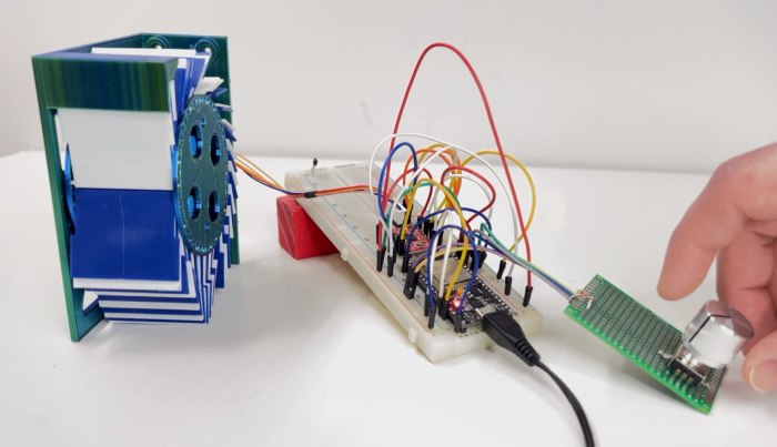
Initial Testing
Once everything was assembled and the web ui was built this is the initial testing:
1 Motor is cool, but how about 10?
To drive 10 motors, we need lots of inputs and outputs. To add more outputs we can use shift registers.
Each split flap requires 1 input for the hall sensor (green) as well as two motor outputs. One for speed (pink) and one for on/off (purple). In total 10 inputs and 20 outputs.
Driving Shift Registers via SPI
To send data out of a shift register you need a clock, data, and latch pin. For clock and data you can use the SPI bus.
The 595 datasheet indicates at 3v you can drive the chip somewhere between 5MHz (@ 2v) and 20MHz (@ 4.5v)!
Here we have the shift register wired up to 8 LEDs. 2 SPI pins and a Latch pin go to the ESP32
Here is a simple pattern alternating 01010101 and 10101010 at 1Hz
We can play with a few parameters to make this transaction happen as fast as possible.
SPI Clock
SPI Bus Initializations / Exclusivity
Latch Pulse Period
Latch Pin Pulse Mechanism
Using a logic analyzer we can see exactly how the data as it is sent to the shift register, and look at the signal timing.
Digital 0 (black) is clock
Digital 1 (brown) is data
Digital 2 (red) is latch which triggers the output signal
Digital 3 (orange) is the motor pulse signal on one output
First we are sending data over the SPI bus at 1MHz. Here you can see the data 01010101 being clocked in.
Motor drivers want pulses so two spi data transmissions and two latch pulses yield one motor pulse on all the outputs. (See image below)
The latch pulses are clearly visible on the Digital 2 line.
All outputs are set to HIGH then all outputs set to LOW as quickly as possible. (See Digital 1).
To drive the motors a pulse with a period around 500Hz (2ms) is required. The motor pulse period is controlled by a hardware timer.
Here are all the channels showing SIPO (Serial In Parallel Out) in action!
All of the above data is transmitted in 6 microseconds.
We want to perform this pulse as fast as possible. To decrease the time spent sending data on the SPI bus we can increase SPI bus speed. 10MHz worked fine on my breadboard.
Optimizing Motor Pulse Length
The A4988 Motor Controller has a min pulse duration of 1us (1MHz).
The TMC2209 Motor Controller has a min pulse duration of 100ns (10MHz)
After shortening the latch pulse time, two SPI write and latch routines complete in 2us. This is within spec of both motor controllers.
Notice at this speed the clock pulses are getting garbled and the second latch pulse isn't displaying at all. We are reaching the limits of this logic analyzer!
Shift Register Variable Frequency (Motor Speed) Output
Making shift register communication faster opens the door to variable frequency output on each channel.
This means each of the 10 motors can move at different speeds / accelerations.
Variable frequencies on each channel can be achieved by using a base frequency (timer) and a counter (clock divider) to skip ticks between output pulses. Giving each channel a different counter value yields a different frequency on each channel. Cool!
The base frequency must be multiple times faster than your desired output frequency range.
Minimizing shift register transaction time allows a wider range of base frequencies to be used.
Here you can see channels 3-7 each have a different pulse period.
Here we slowed the output timer way dowm from 20KHz (read more below) to 16Hz
I selected the base frequency of 20KHz.
Counter values between 26 and 43 yield output frequencies between 750Hz and 450Hz respectively. This is the full operating range of our stepper motors.
At 20KHz we get 17 (43 - 26) different speeds we can use.
At each tick we only perform one transition of the output pulse. To calculate output frequency from base frequency use the formula:
Output Frequency = Input Base Frequency / (Tick Count + 1)
Notice increasing the base frequency yields increased resolution of the steps.
The resolution of the steps is a linear function of the base frequency. At 20KHz the resolution between these tick counts scales from 28Hz and 10Hz.
The variable motor frequency has one drawback. It will limit the max number of shift registers we can communicate with. For our purpose we will only need 3 shift registers, but it is important to be aware of your limitations.
1.25us to communicate with one shift register
tick interval of 50us
50 / 1.25 = 40 max number of shift registers at 20KHz
Below is the full table of input base frequencies and output frequencies.